Key takeaways
- A thermal mass flow controller reads correctly only for the gas it was calibrated on; any other gas shifts the scale.
- MKS publishes gas correction factors relative to nitrogen (N2 = 1.00) — for example argon 1.39, CO2 0.70, SF6 0.26.
- For a unit calibrated on a gas other than nitrogen, divide the factor of the gas you flow by the factor of the calibration gas.
- A gas mixture is not a simple weighted average of the factors — MKS gives a separate calculation.
- Published factors are theoretical; for the best accuracy, the manufacturers recommend calibration on the actual gas.
A gas correction factor (GCF) tells you how much real flow of one gas a thermal mass flow controller (MFC) delivers when it was calibrated on another. If your MFC is calibrated for nitrogen and you flow argon, helium or CO2 through it, the reading and the setpoint no longer mean what the label says — the GCF is the number that converts between them.
This guide explains why the correction is needed, how to apply a published factor, and where a factor stops being accurate enough. It covers thermal MFCs, the type the published GCF tables are written for.
Why a thermal MFC needs a correction factor
A thermal MFC measures flow by how the gas carries heat through its sensor. Different gases carry heat differently. Brooks Instrument describes the result: when a thermal MFC operates with a gas other than the one it was calibrated for, a scale shift occurs between the output signal and the mass flow, because the two gases have different heat capacities.
In practice: the electronics, the valve and the signal are the same, but 100% of full scale is a different amount of gas. The correction factor captures that difference as one number.
How to read a gas correction factor table
MKS Instruments publishes a table of theoretical gas correction factors for thermal-based MFCs, all expressed relative to nitrogen. Nitrogen is 1.00, so a factor above 1 means the unit passes more of that gas than its nitrogen scale shows, and a factor below 1 means less. A few values from the MKS table:
- Argon (Ar) — 1.39
- Helium (He) — 1.45
- Hydrogen (H2) — 1.01
- Oxygen (O2) — 0.993
- Methane (CH4) — 0.72
- Ammonia (NH3) — 0.73
- Carbon dioxide (CO2) — 0.70
- Silane (SiH4) — 0.60
- Carbon tetrafluoride (CF4) — 0.42
- Sulfur hexafluoride (SF6) — 0.26
The MKS table defines standard conditions as 0 °C and 760 mmHg (14.7 psia), and MKS defines sccm — standard cubic centimeters per minute — against the same reference of 0 °C and 760 Torr. Keep that in mind if the rest of your process works to a different standard. For some gases MKS gives no number at all and asks you to consult its applications team; nitrogen dioxide is one.
Applying the factor: worked examples
Unit calibrated on nitrogen
Multiply the nitrogen full scale by the factor of the gas you flow. A 1,000 sccm N2 unit with argon (1.39) gives about 1,390 sccm of argon at full scale. The same unit with SF6 (0.26) gives about 260 sccm of SF6.
Unit calibrated on another gas
MKS’s rule: take the GCF of the gas you are flowing and divide it by the GCF of the gas the MFC was calibrated for. MKS’s own example is a 100 sccm argon unit used for CO2: 0.70 / 1.39 = 0.50, so at full scale it flows about 50 sccm of CO2.
Same gas as the calibration
If you flow the gas the unit was calibrated for, the factor is 1 — no correction.
Gas mixtures are not a weighted average
It is tempting to average the factors of a mixture by their share of the flow. MKS says plainly that this is wrong: the GCF of a mixture is not the weighted average of the components’ GCFs. Its calculation uses, for each gas, the fractional flow (the fractions must add up to 1.0), a molecular structure factor, the standard density and the specific heat.
MKS lists the structure factors by molecule type: 1.030 for monatomic gases, 1.000 for diatomic, 0.941 for triatomic and 0.880 for gases with four or more atoms. Densities and specific heats for most gases are listed in MKS MFC manuals. Use the full MKS equation, or ask the manufacturer to run it for your mixture.
When a factor is not accurate enough
MKS describes its values as theoretical and notes that a non-linearity may exist between a nitrogen calibration and the actual flow of a process gas — the factor is a good conversion at one point, not a guarantee across the whole range.
Brooks Instrument states that the highest accuracy always comes from calibration on the actual gas. Changes that need a different orifice or restrictor — a new flow range, operating pressure or gas condition — need the manufacturer’s technical support, not a factor.
So a GCF is a good tool to check whether a unit you already have, or one you are buying, can cover your flow on your gas. For a critical process recipe, plan on recalibration or a unit calibrated for the actual gas.
Before you buy a replacement MFC
Write down, from the label or the calibration certificate of the unit you are replacing:
- The manufacturer part number — see how to find your part number.
- The calibration gas and the full-scale range (for example “N2 1000 SCCM”).
- The gas you actually flow, and your normal and maximum flow.
- The signal and communication type the tool expects (analog, DeviceNet or other).
With the calibration gas and range of a candidate unit, the factors above tell you roughly what it will deliver on your gas. Many of our listings name the calibration gas and range in the title — browse mass flow controllers, or, if you cannot find the exact number, send it to us through Request a Part. Questions about a listing: contact us.
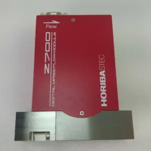
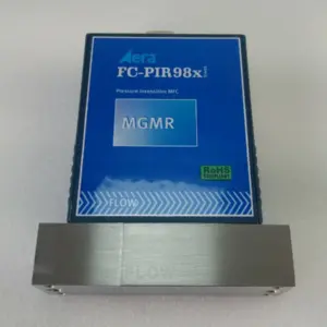
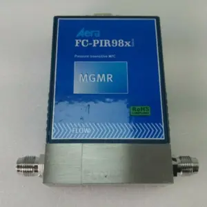
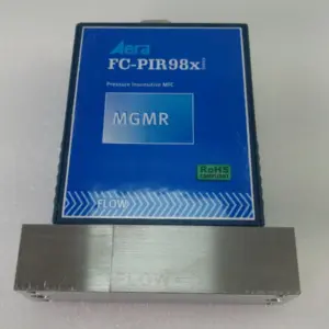
Some flow controllers in the catalog are pressure-type rather than thermal. The thermal GCF tables in this guide are not written for them — check that manufacturer’s documentation for gas conversion.
Frequently asked questions
What is a gas correction factor for a mass flow controller?
It is a number that converts the flow a thermal MFC shows for its calibration gas into the real flow of another gas. MKS publishes factors relative to nitrogen, which is 1.00.
Do I multiply or divide by the correction factor?
For a nitrogen-calibrated unit, multiply the reading or full scale by the factor of your gas. For a unit calibrated on another gas, first divide your gas's factor by the calibration gas's factor, then multiply by that result.
What is the gas correction factor for argon and CO2?
In the MKS table, relative to nitrogen, argon is 1.39 and CO2 is 0.70. An argon-calibrated unit used for CO2 therefore has an effective factor of about 0.50.
Can I average the factors for a gas mixture?
No. MKS states that a mixture's factor is not the weighted average of its components and gives a separate equation using fractional flow, structure factor, density and specific heat.
Is a correction factor as accurate as calibrating on the real gas?
No. MKS calls its factors theoretical and warns of possible non-linearity, and Brooks states that the highest accuracy comes from calibration on the actual gas.
Do these factors apply to pressure-based flow controllers?
The published tables cited here are for thermal-based MFCs. For a pressure-type controller, use its manufacturer's gas conversion data.
Sources
- MKS Instruments — Gas Correction Factors for Thermal-based Mass Flow Controllers (table relative to nitrogen, standard conditions, non-linearity note) (opens in a new tab)
- MKS Instruments — Flow Measurement & Control FAQ (mixture GCF, structure factors, different calibration gas, Ar→CO2 example, sccm definition) (opens in a new tab)
- Brooks Instrument — Mass flow controller gas correction factors (scale shift from heat capacity, calibration on actual gas, Technical Services for orifice/range changes) (opens in a new tab)